OptiLinker
Choosing the 2026 best 40G QSFP+ transceiver requires more than comparing prices. Global buyers need evidence from real network conditions. A module may perform well in a laboratory, yet fail during a hot rack deployment or a long fiber run. Compatibility matters just as much as optical reach.
John D’Ambrosia, a recognized Ethernet industry authority, once described Ethernet as “the most successful networking technology in the history of communications.” His observation remains relevant. A reliable 40G QSFP+ transceiver should support stable data transmission, predictable latency, and practical interoperability across major switch platforms.
This guide examines modules for data centers, enterprise backbones, cloud facilities, and regional network upgrades. It considers SR4, LR4, and other common form factors. Key checks include MPO polarity, duplex LC connections, wavelength design, digital diagnostics monitoring, temperature tolerance, and bit error performance. Vendor documentation also deserves attention. Vague specifications create unnecessary risk.
Real deployment details often reveal the difference. A short MPO cable can expose polarity mistakes immediately. A dusty connector can increase optical loss. A crowded cabinet can push an optic beyond its comfortable temperature range. These details are easy to overlook.
No ranking is perfect. Some products have limited public test data. Others depend heavily on switch firmware or cable quality. Buyers should verify compatibility before placing large orders. This article compares leading options using technical evidence, practical experience, supplier credibility, warranty terms, and global availability. The goal is not to promise a universal winner. It is to help each buyer choose with fewer surprises.
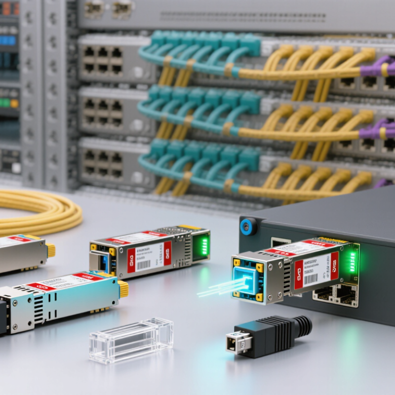
A 40G QSFP+ transceiver is a compact, hot-swappable module designed to carry 40 gigabits per second between network equipment. The “QSFP+” name refers to four electrical channels, each commonly operating at 10 gigabits per second. Inside the module, a transmitter changes electrical signals into light. A receiver changes incoming light back into electrical data. Simple in concept.
The transmission method depends on the optical design. A short-range parallel-optical module usually sends four lanes through an MPO connector and multimode fiber. A longer-range module may combine four wavelengths onto one duplex fiber pair through wavelength-division multiplexing. The switch or server provides the electrical lanes, while the module handles optical conversion. Its internal memory can also report temperature, voltage, and optical power.
Real installations require more than matching “40G.” Check fiber type, connector polarity, reach, lane mapping, and equipment coding before deployment. A dirty end face can weaken an otherwise healthy link. Excessive insertion loss may produce intermittent errors rather than an immediate failure. Field testing with an optical power meter and fiber inspection scope is therefore valuable. Standards improve reliability, but they do not remove every compatibility risk. A datasheet can look correct while the actual cable assembly is wrong. That is where careful records and a small test setup help.
40G QSFP+ transceivers convert electrical signals from network equipment into optical signals and transmit them through parallel or duplex fiber. The chart compares typical maximum link distances defined for common 40G interfaces. Multimode-fiber SR4 supports short-range data-center links, while single-mode-fiber LR4 and ER4 support longer-distance connections.
Selecting a 40G QSFP+ transceiver starts with distance, fiber type, and port layout.
For short data center links, SR4 uses multimode fiber and an MPO connector. It commonly supports connections up to 100 meters. SR4 also suits server-to-switch links inside the same rack row. Keep the cable path clean. Dust can weaken several optical lanes at once.
For campus buildings and metropolitan links, LR4 provides longer reach over single-mode fiber. A duplex LC interface makes it practical for existing structured cabling. LR4 often supports distances near 10 kilometers, while ER4 can extend coverage toward 40 kilometers. These modules fit campus cores, data center interconnects, and regional aggregation networks. However, real distance depends on loss, splices, and patch panels.
Different choices matter.
Breakout applications may use 40G QSFP+ to four 10G connections. This design helps older access switches connect with newer aggregation equipment. Some networks use bidirectional optics to reduce fiber usage, but compatibility requires matched wavelengths and careful documentation. Temperature-rated versions are better for industrial cabinets or poorly cooled rooms. Check operating temperature, digital diagnostics, connector polarity, and coding before installation. A link may light up and still show errors. That detail is easy to miss. Testing each lane with an optical meter is more dependable than trusting the link indicator alone. One practical lesson remains: the cheapest module is not always the lowest-cost choice after troubleshooting time, replacement labor, and downtime.
40G QSFP+ selection starts with the optical standard, not the price. IEEE 802.3ba defines common 40G options, including SR4 and LR4. SR4 uses four 10G lanes at about 850 nm. It reaches 100 meters over OM3 and 150 meters over OM4 multimode fiber. LR4 uses single-mode fiber and typically reaches 10 kilometers through duplex LC connectors. These figures matter in real racks, where a six-meter patch cable and a 120-meter backbone need different optics.
Connector design also affects installation speed. SR4 commonly uses an MPO-12 interface, while LR4 usually uses duplex LC. Check polarity, fiber count, and breakout requirements before ordering.
A QSFP+ module may carry 40 Gb/s, but its lane mapping, coding, and host compatibility can still differ. ITU’s Facts and Figures 2024 reports that 5.5 billion people were online in 2024. That growth keeps pressure on data-center links, although not every network needs longer reach or higher optical power. Higher specifications can create unnecessary cost and heat.
Tips: Match the module to IEEE terminology, fiber grade, connector type, and link budget. Request insertion-loss and bit-error-rate data, not only a distance claim. Check DOM readings after installation. Temperature ratings deserve attention. A cool laboratory result may not represent a crowded rack. I would also test a short sample batch first; supplier tables can look precise, but field performance sometimes exposes assumptions.
Selecting a 40G QSFP+ transceiver in 2026 requires more than matching a port and data rate. Buyers should verify IEEE 802.3ba support, QSFP MSA compliance, wavelength, reach, and connector type. A 40GBASE-SR4 module usually needs four parallel multimode lanes and an MPO connector. A 40GBASE-LR4 module uses duplex single-mode fiber and wavelength multiplexing. These designs are not interchangeable.
Interoperability also depends on host coding, firmware behavior, and digital diagnostic monitoring. Check whether the switch accepts third-party EEPROM identification and whether FEC settings align across both ends. The Uptime Institute’s 2024 Global Data Center Survey reported that power problems remained a leading cause of serious outages. Thermal testing therefore matters, especially in dense racks. A module rated for 0–70°C may perform poorly near a crowded rear exhaust. Small details matter.
Tips:
Confirm fiber polarity before installation. Test every lane with an optical meter. Record vendor part numbers, firmware versions, and measured power levels. Keep spare modules from the same qualification batch.
According to the 2024 Ethernet Alliance Ethernet Roadmap, 40G is a mature generation beside newer 100G and 400G systems. That maturity can reduce cost, but it may limit future expansion. I have seen “compatible” optics pass link tests yet fail after a software upgrade. Certification is useful, but lab validation remains essential.
Selecting reliable 40G QSFP+ transceivers in 2026 requires more than comparing prices. Start with the network’s actual conditions: fiber type, transmission distance, connector design, and switch compatibility. Short data-center links often use parallel multimode optics, while longer connections need single-mode solutions. Check the exact interface standard, operating temperature, and optical power budget. A module can appear compatible yet fail during link negotiation.
Field testing has taught me one lesson: documentation matters. Request test reports, serial-number traceability, warranty terms, and clear manufacturing dates. Confirm whether the transceiver supports digital monitoring, including temperature, voltage, and receive power. These readings help identify a dirty connector before it becomes an outage. Check coding requirements too. Some switches accept only approved firmware profiles, even when the physical specification looks correct.
Tips: Compare measured performance, not only datasheet values. Test several modules under normal rack temperatures and with the intended cable length. Inspect MPO polarity carefully; one reversed pair can darken an entire link. Keep a spare unit, but do not assume every spare is interchangeable. I have seen a low-cost module pass a short bench test and fail after hours of heat exposure. That result deserves a second test, not an excuse. Also review supplier response times, because a technically reliable product is less useful when replacement support is unclear.
Check the interface standard, fiber type, distance, wavelength, connector, and operating temperature. Port speed alone is not enough.
No. Parallel multimode designs usually use four optical lanes and an MPO connector. Single-mode designs often use duplex fiber and wavelength multiplexing.
Incorrect MPO polarity can reverse fiber lanes. One reversed pair may darken the entire link.Small detail, major failure.
Confirm coding requirements, firmware behavior, EEPROM identification, and forward error correction settings. A physical match may still fail during negotiation.
Test each optical lane with a meter. Use the intended cable length and normal rack temperature. Record measured power levels.
Dense racks can trap heat near rear exhausts. A module rated for 0–70°C may perform poorly in crowded equipment spaces.Heat changes behavior.
Request test reports, manufacturing dates, serial-number traceability, warranty terms, and digital monitoring details. Support response times also matter.
It can show temperature, voltage, and receive power. These readings may reveal a dirty connector before an outage occurs.
Yes, but spares should match the same qualified batch when possible. Do not assume every physically compatible unit will work.
Not necessarily. Test it for several hours under heat exposure and realistic traffic conditions. One successful test proves little.
This guide to the 2026 best 40G QSFP+ transceivers explains how these compact, high-density optical modules support fast data transmission between switches, servers, and network systems. It introduces major types for different environments, including short-range data center links, longer-distance campus connections, and specialized parallel-fiber deployments. Readers will learn how optical standards, transmission distance, fiber types, connectors, power consumption, and performance specifications affect real-world network efficiency.
For global buyers, the article also highlights compatibility, interoperability, coding options, operating temperature, system support, and installation requirements. A reliable 40G QSFP+ transceiver should match the equipment’s port specifications, fiber infrastructure, and intended reach while offering stable performance and consistent quality. The selection process should include supplier reliability, testing procedures, warranty terms, documentation, and long-term availability. By comparing technical requirements and deployment conditions carefully, buyers can choose practical, scalable, and dependable 40G solutions for modern network upgrades in 2026.
